How to “neuter” a Tuya Smart Switch so it can’t turn-off.
I wanted to use a Tuya Smart Switch to monitor a fridge to detect a problem (eg complete power failure, or unusual compressor cycling). However, I didn’t want to run the risk of the switch turning off and creating the very problem I am trying to detect.
So the aim was to open the switch up and bridge the relay contacts so it could not turn the power off. Effectively turning the smart switch into a power monitor only.
IMPORTANT: Before cutting open the case, test the switch thoroughly – including the earth through-connection (I had 2 units where the earth pin had not been soldered). Note that the device switches the neutral – not the active.
The switch is glued into a casing at both ends. Which end to try cutting out first? I chose the wrong one of course.

I used a saw blade on my Dremel, but had to angle it inwards to hit “free air” (cutting directly down didn’t work). Around the corners, I used an engraving tool.

IMPORTANT: When cutting on the side with the switch, angle the blade well in towards the centre of the device (eg 45 degrees) to avoid messing-up the plastic of the pushbutton cover.


The relay is a JZC-11FH 005-1H1L. It switches the neutral conductor (active is straight-through).

To remove the PCB to get good access to the bottom of the relay meant unsoldering the incoming active, neutral and earth pins from the PCB – and they are big solid lumps of copper. I decided that was too hard, so I tackled it from side between the PCB and the case.


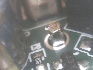
Before you glue the unit back together, check the earth pin has been soldered (unlike this one)

If the cover is not very securely re-glued to the PCB, it is possible the cover might pull-off and leave the PCB behind still plugged into mains voltage – leaving the insides all exposed and dangerous. To try and prevent this (inside the unit), I applied silicone around the edges of the PCB to help it adhere to the housing (which I could only do because I had removed both ends). If you don’t take the top off, you will need some strong adhesive on the bottom to prevent this from happening.
For the subsequent units I modified, I did not cut the top off. To secure the bottom, I applied heaps of silicone around the inside of the casing about where the PCB sits, and more on the edge of the PCB. Hopefully, when the PCB is pushed back into the case, all this silicone will be enough to keep the case from pulling-off. (This certainly secures it well – I had occasion to try to get one apart again – and couldn’t.)
If you do apply silicon around on top of the PCB, make sure you don’t cover-up the blue, surface mount LED (like I did originally!).